Measuring the Input Capacitance of an Op Amp to Reduce Noise
Operational amplifiers are widely used in various electronic circuits. They are used to amplify small voltages for further signal processing. Applications such as smoke detectors, photodiode transimpedance amplifiers, medical devices, and even industrial control systems require the lowest possible operational amplifier input capacitance because this affects the noise gain, which in turn affects the stability of the system, especially with high frequencies and high gains.
What should you look for when measuring operational amplifier input capacitance?
It is important to ensure that the measurement accuracy is not affected by the stray capacitance and inductance of the PCB or the test fixture. You can minimize these issues by using low-capacitance probes, using short connections on the PCB, and avoiding large ground planes under signal traces.
Operational amplifiers are widely used in various electronic circuits. They are used to amplify small voltages for further signal processing. Applications such as smoke detectors, photodiode transimpedance amplifiers, medical devices, and even industrial control systems require the lowest possible operational amplifier input capacitance because this affects the noise gain, which in turn affects the stability of the system, especially with high frequencies and high gains.
In order to maximize the accuracy of the corresponding circuit, we need to know the input capacitance of the operational amplifier. However, this information is not usually available in the data sheet, so it needs to be determined individually. This can be difficult because in many cases the input capacitance is only a few pF.
Table 1 lists several different op amp examples and their respective input capacitance values.
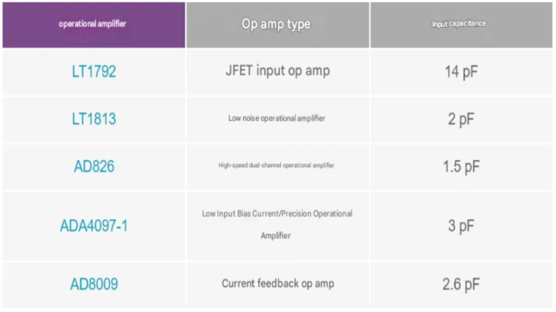
Table 1. Different op amps and their input capacitance values
How to determine input capacitance
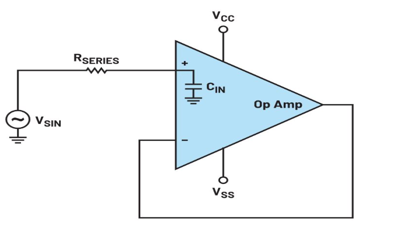
Figure 1 shows a simple way to determine op amp input capacitance by adding a resistor in series with the op amp input (RSERIES). This forms a first-order low-pass filter whose frequency response can be recorded by a network analyzer. The input capacitance can be calculated from the frequency response. The resistor RSERIES is typically between 10 kΩ and 100 kΩ.
When recording the frequency response, it is important to ensure that the measurement accuracy is not affected by stray capacitance and inductance of the PCB or the test equipment.
To improve the measurement resolution, stray capacitance should be kept as low as possible. Low capacitance (<1 pF) FET probes are recommended.
The PCB capacitance to ground should be kept as low as possible, which can be achieved by ensuring that there is no ground plane underneath the signal traces and series resistors.
In addition, lines and (resistor) leads should be kept as short as possible to avoid additional error sources such as series and parasitic inductance.
Figure 2 shows a possible test configuration with a network analyzer and a power divider.
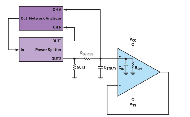
Test setup for determining the input capacitance of an op amp.
The power divider splits the signal. The signal is fed 1:1 to the input of the network analyzer as is and after an inserted low-pass filter reaches the input of the op amp. The network analyzer then generates a frequency response based on the difference between these two signals.
To perform the measurement, the stray capacitance CSTRAY needs to be determined. First, the signal is applied to the board without the op amp installed. Based on the resulting Bode plot, CSTRAY is calculated using Equation 1:
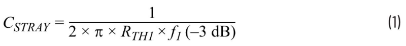
f1(–3 dB) is the –3 dB corner frequency measured without the op amp using a network analyzer, and RTH1 is a function of the inserted series resistor (RSERIES), the input termination resistor (50 Ω), and the 50 Ω source impedance of the power divider (Thévenin equivalent):

Then, mount the op amp on the PCB.
Since the stray capacitance of the PCB is in parallel with the input capacitance of the op amp, add CIN to Equation 1, as shown in Equation 3:
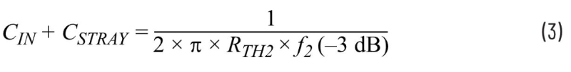
where f2(–3 dB) is the –3 dB corner frequency measured with the op amp using a network analyzer, and RTH2 is a function of the inserted series resistance, the input termination resistance (50 Ω), the output resistance of the power divider (50 Ω), and the common-mode input impedance of the op amp (RCM):

In general, for op amps with CMOS inputs, RSERIES << RCM. Therefore, RTH2 ≈ RTH1, and Equation 3 can be rewritten as Equation 5:
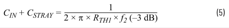
Then, the op amp input capacitance can be determined using Equation 1 and Equation 5.
The op amp input capacitance is difficult to measure. It is usually only a few pF, and parasitics in the test setup can distort the measurement. The input capacitance can be easily determined using a small test setup and suitable measurement equipment consisting of a network analyzer and a power divider: First, the stray capacitance (error capacitance in the test setup) is determined, and then the combined capacitance of the op amp circuit (error capacitance and input capacitance) is determined from the frequency response. Based on the above formula, the actual input capacitance of the op amp can be calculated.
Sign up to our newsletter
Receive our latest updates about our products & promotions